Drawing a Floor plan
There are different approaches to draw floor plans on Revit. Either by importing from AutoCAD or drawing it directly on Revit.Direct drawing on Revit
Step 1: Open Autodesk Revit, select "New Project", then click on Project and OK.Step 2: The next thing is set your levels, it will determine the height of your building (Setting out your parameters) and it will also give you guildelines when placing or creating a component. But before doing that, you need to make sure your units are set; Type shortcut "UN", you can either set it to inches or millimeters.

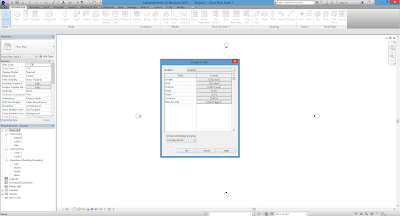
Then go to elevation on the Project browser, double click on South, then you will see to lines drawn showing Level 2 & Level 1, move your cursor to Level 1 set at 0mm and rename Level 1 to NGL (Natural Ground Level), move your cursor to Level 2 rename Level 2 to Level 0 and set it at 450mm, that stands for the height of the steps when entering into the building.
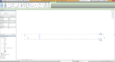
Then move your cursor where you have Level and Grid, click on Level, move your cursor to the end point of the Levels, click on it and move it to the end point of the Level 0; the figure is shown below.

From the point of Level 0, click and drag to the end point, click on the new Level and rename it to Level 1. Then, click on Level 1 and edit the height to 3100mm (3.1m). Then do same for the new Level you want to create and rename as Level 2. The illustration will be shown below:
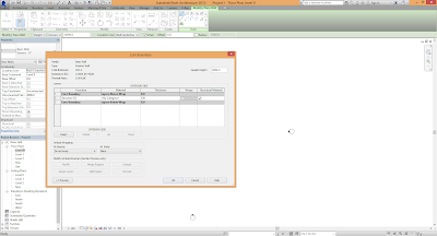
Step 3: On the Project Browser, double click on Level 0 on Floor Plans, that shows your plan view, you start drawing your floor plan. Before you start that, move your cursor to Architecture taskbar and click on Wall (WA), go to Properties and click on Edit Type the Type Properties window will pop out, next click on Duplicate the essence of duplicating the wall type is in case you may need to use that type of wall for a different use. Duplicate the wall and name it as Exterior Wall. Then click on Edit where you have Parameter and Value, it will show another window with a table showing Core Boundary-Structure-Core Boundary; under Structure, change the wall thickness to 230mm or 225mm depending on the wall function, ignore the other Parameters on Core Boundary, when done click Ok, under Type Properties click Ok. The illustration is shown below:

When done, before drawing your plan, move your cursor to Properties, you will see Base constraint, Top constraint, Location line etc. your Base constraint is set at Level 0 that’s fine 👍 your Top constraint shows Unconnected, set it to Level 1, this will then guide you on the height of your building. So this is where you can start drawing your floor plan.
Place the window at the appropriate areas of your floor plan after adjust and edit the window where necessary. For instance, a toilet window, click on the window and edit or if you want to change the window, you can load another family of window and place on the wall (use the window type that best fits for a toilet) after placing it you can edit the width of the window, click on the window go to properties and click on edit type, then click on Duplicate and name is as Toilet Window_1 (for clarity reasons). Then, change the width of the window to 900mm or 800mm, the height of the window, change it to 500mm, then click OK.
For the other window types, change the sizes of the window where necessary, click on one of them, go to properties and click on edit type and click on duplicate, and name it as Window_1. Then change the width and height of your choice.
Step 8: The final step is to create a roof. On your project browser, double click on Level 1. On the properties tab, always make sure the underlay is set to Level 0, this will give you a guideline when drawing a roof or drawing another floor plan. After its been set, move your cursor to roof, click the drop down, there you will see roof by footprint, roof by extrusion, roof by face; click on roof by footprint. Then use pick lines, on the offset you can either use 900mm or 1200mm overhang depending on the building function, type 1200mm and click at the outer edge of the wall. After doing that, you edit the roof by clicking on edit type on the properties menu, duplicate the roof and name it as Roof_1 and click OK. Click on edit under the edit type menu and change the roof thickness to 20mm or less and then click OK.
On the sketch roof, click on one of the pink or magenta lines, automatically when sketching a roof on plan view slopes are defined, so click on the line and reduce the slope angle to any angle of your choice. After doing that you click on finish ✔. The slope angle determines the height of your roof. When all lines on the lines have defined slopes it is literally a hip-roof.
Now you have created your building on Revit, this post has given you a little insight on the use of Revit software to execute a project, in the next post you will learn how to create a facade on a building using the Revit software.
Then move your cursor where you have Level and Grid, click on Level, move your cursor to the end point of the Levels, click on it and move it to the end point of the Level 0; the figure is shown below.

From the point of Level 0, click and drag to the end point, click on the new Level and rename it to Level 1. Then, click on Level 1 and edit the height to 3100mm (3.1m). Then do same for the new Level you want to create and rename as Level 2. The illustration will be shown below:
Step 3: On the Project Browser, double click on Level 0 on Floor Plans, that shows your plan view, you start drawing your floor plan. Before you start that, move your cursor to Architecture taskbar and click on Wall (WA), go to Properties and click on Edit Type the Type Properties window will pop out, next click on Duplicate the essence of duplicating the wall type is in case you may need to use that type of wall for a different use. Duplicate the wall and name it as Exterior Wall. Then click on Edit where you have Parameter and Value, it will show another window with a table showing Core Boundary-Structure-Core Boundary; under Structure, change the wall thickness to 230mm or 225mm depending on the wall function, ignore the other Parameters on Core Boundary, when done click Ok, under Type Properties click Ok. The illustration is shown below:
 |
| Wall Edit |

When done, before drawing your plan, move your cursor to Properties, you will see Base constraint, Top constraint, Location line etc. your Base constraint is set at Level 0 that’s fine 👍 your Top constraint shows Unconnected, set it to Level 1, this will then guide you on the height of your building. So this is where you can start drawing your floor plan.
Now you will have to always
save your work, every 30 minutes a small window pops out to save your project,
to avoid data loss.
Step 3: When
done drawing your floor plan on Level 0,
move your cursor to the Project
Browser and double click on NGL, click
on Wall (WA) and move your cursor to Properties and set your top constraint to Level 0, draw your plan again on the
previous plan. That wall serves as a step between the natural ground level and
the floor inside the building.
Step 4: The next step is to create a window on your project. You can either load
a window or use curtain wall. At this stage I will teach you how to load a
window. First, move your cursor to the Architecture bar and click on window, go
to Load Family under Modify|place
window, a load family window will pop out showing different folders from the
Revit Library, scroll down and you will see windows folder, double click on it,
it will give you different categories of windows, pick any window of your
choice, be it casement window, sliding window or any other type of window. For
example, I will pick casement window. The illustration is shown below:
Place the window at the appropriate areas of your floor plan after adjust and edit the window where necessary. For instance, a toilet window, click on the window and edit or if you want to change the window, you can load another family of window and place on the wall (use the window type that best fits for a toilet) after placing it you can edit the width of the window, click on the window go to properties and click on edit type, then click on Duplicate and name is as Toilet Window_1 (for clarity reasons). Then, change the width of the window to 900mm or 800mm, the height of the window, change it to 500mm, then click OK.
For the other window types, change the sizes of the window where necessary, click on one of them, go to properties and click on edit type and click on duplicate, and name it as Window_1. Then change the width and height of your choice.
Step 5: The next step is to create a Door. On your Architecture bar, click on Door or type DR shortcut, you will see a plain single flush door, go to Load family, there are different
folders showing canopy, domestic, doors, furniture etc. double click on doors, and
pick the door of your choice and click on Ok,
then place the door on the designated areas. That’s how you will be loading
different types of doors.
Step 6: The next step is to create floor
still on Level 0, move your cursor to the Architecture tab and click on Floor, there are different types of
lines: single line, rectangle, pentagon, ellipse, pick line, etc. click on pick line or you can use the single line, then click on the inner
part of your wall. After sketching the TR shortcut to trim out the outer edges. The illustration is shown below:
On floor while on edit/sketch
mode, go to properties and click on edit type, click duplicate and name the
floor as Floor_1 then click ok. Click on edit beside the structure
column and change the thickness to 150mm, and click ok for all. After doing
this click on Finish (✔ the green button), this
statement pops up “Would you like walls
that go up to this floor’s level to attach to its bottom”? Just ignore by
clicking the ❌ button. Your floor is created.
Step 7: The next step is to create steps for entering the building.
You can either use floors or stairs. I prefer using floor to create steps
because it will be very easy to edit and adjust if there are any adjustments
needed in the project.
On your Project Browser, double click on NGL click on Floor, set your height offset on 0mm and draw, click
finish, then repeat same but the height offset will change to 150mm then you
sketch floor where you want your steps to be on your floor plan, repeat same
and change the height offset to 300mm, your steps are created 👌👍.
Step 8: The final step is to create a roof. On your project browser, double click on Level 1. On the properties tab, always make sure the underlay is set to Level 0, this will give you a guideline when drawing a roof or drawing another floor plan. After its been set, move your cursor to roof, click the drop down, there you will see roof by footprint, roof by extrusion, roof by face; click on roof by footprint. Then use pick lines, on the offset you can either use 900mm or 1200mm overhang depending on the building function, type 1200mm and click at the outer edge of the wall. After doing that, you edit the roof by clicking on edit type on the properties menu, duplicate the roof and name it as Roof_1 and click OK. Click on edit under the edit type menu and change the roof thickness to 20mm or less and then click OK.
On the sketch roof, click on one of the pink or magenta lines, automatically when sketching a roof on plan view slopes are defined, so click on the line and reduce the slope angle to any angle of your choice. After doing that you click on finish ✔. The slope angle determines the height of your roof. When all lines on the lines have defined slopes it is literally a hip-roof.
Go to your 3d view on the Quick Access Toolbar where you see this
symbol of a house, click on it, it will give you a 3d view, if you feel your
roof height is to low, click on your roof and edit, then change the slope angle
to 20° and click finish. You will see something like your roof has been
truncated but it hasn’t nothing to panic. Move your cursor to the properties bar,
scroll down under Extents you will
see View Range, click on edit the
view range window will pop out, then you will play around with the Top and cut
plane: Change the Top and cut plane offset to 2900mm click on apply you will see your roof plan is
back to normal, then click on Ok. So
the roof created 👍.
Now you have created your building on Revit, this post has given you a little insight on the use of Revit software to execute a project, in the next post you will learn how to create a facade on a building using the Revit software.
Also Read


Comments
Post a Comment